DATE: 02-16-2025 TIME: 2:39 p.m. – 5:25 p.m. ~ 3:00
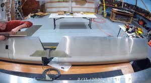
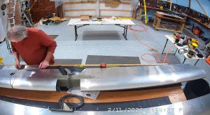
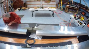
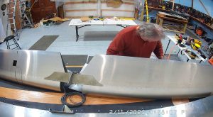
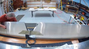
Continuing the Zenith 750 SD elevator assembly today began by making sure the bench was clean and then setting up to assemble the trim tab. In the Zenith IPL document this is on sheet HE-04A. The “bottom” of the trim tab is the fold with the rivet holes along the length.
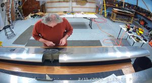
You shouldn’t have any problem correctly orienting the trim tab horn or the edge doublers as they will only fit the correct way. The horn has an A6 rivet in the front. Make sure you align the edge doublers with the edge of the skin and the holes should align correctly.
The instructions say to file, if necessary, a radius along the front and rear edges of the center doubler but that did not appear necessary to me and once installed, I do not see any issues.
I did take some time to deburr holes in order to keep the hinge and tab assembly as flat as possible.
The piano hinge then needs to be clecod to the trim tab between the lower skin and the first fold. There is a notch on the side of the hinge that is attached to the elevator. The other thing to note is that the hinge pin is on the upper side of the tab, which doesn’t seem to make sense until it is assembled.
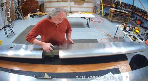
This whole process doesn’t take long and then the only step left really is to install the trim tab servo.
The servo comes in a separate box with all of the pins and rods required. The first thing you have to do is trim the rod length so that the overall length from rod end hole to rod end hole is 148mm which is shown on drawing SD75-HE-04.
The instructions go on to say to attach the servo to a battery so that the servo is completely extended. Attach the rod to the servo and then cleco the servo into the left elevator to the top skin.
When I was attaching the rod end to the trim tab horn I found that it would not swivel freely so I will have to remove a little material from the horn. You can’t remove material from the rod end so it must be from the horn material if you have a similar issue.
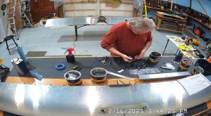
At this point, the only thing left is to rivet the servo in place, attach the wiring making a chart of the colour connections because the colours in the wire are not the same as the wires protruding from the servo, and then adjust the rod so that you have a 30° deflection in both the up and down positions, +- 2°. You also need to check that the rod moves freely without touching the elevator skin and if this is not the case, remove some of the skin material.
I decided as I was going through this process that I did not like the idea of riveting the servo in place nor crimping all the wires together, nor riveting the cover plate in place as this would require drilling out rivets should I need to get to, and / or replace the servo. Consequently, I purchased 6-32 nut plates and screws for the cover plate, a 6 pin connector with pins for 24 gauge wire which is the gauge on the servo, and 6-32 screws and nuts for the servo. These screws won’t go through the servo mounting holes as is but the manufacturer says it is OK to drill those holes to accommodate a 6-32 screw. This does mean that I will have to dimple the rivet holes for the nutplates but I did not buy countersunk screws on the basis that the heads won’t be any worse than the rivet heads specified by Zenith. I have enough solid rivets that I can use those to attach the nut plate but I may just use MK319-BS rivet if the length is correct. I will have to see how that works out.
As of right now I have not completed this process as I am waiting for the parts to arrive. I definitely will use the 6 pin connector but I may still use rivets rather than the screws and nuts / nutplates, depending on how I like it when I start the assembly.
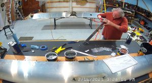
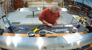
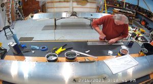
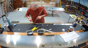
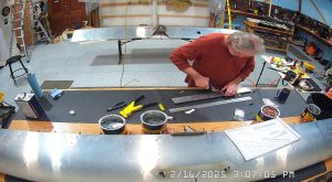
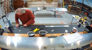
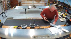
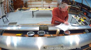
Here are the photos of the process to-date.