Tailcone Assembly – Page 10-2, 10-3, 10-4, 10-5

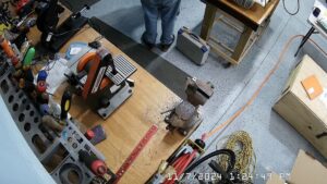
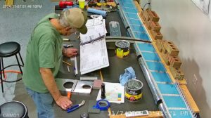
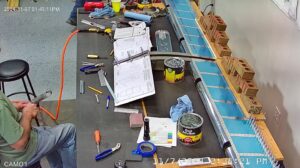
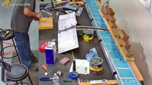
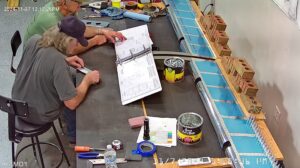
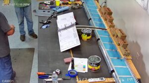
DATE: 11-07-2024 TIME: 1:00 – 4:30 ~ 3:30

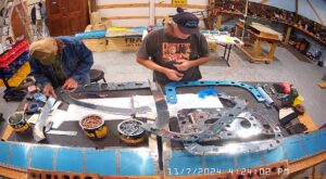
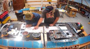
Vans refers to this section as the tailcone assembly section but all the relevant parts are labeled F for fuselage.

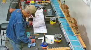
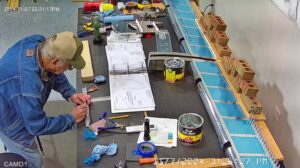
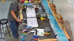
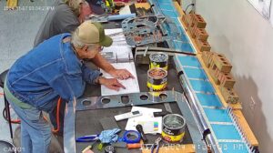
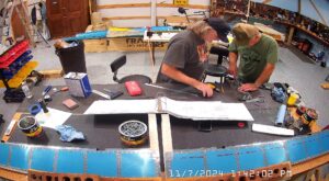
We had previously taken the vinyl off F-1012A and F-1012B as instructed in step 2 and deburred them so we started back at step 1 by locating the tie down bar aluminum AEX TIE DOWN BAR X 7.500 which was not labeled. It’s pretty frustrating to have so many pieces not labeled. Hopefully Vans is doing a better job since recovering from Chapter 11.

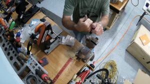
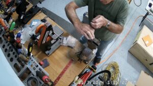
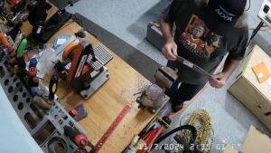
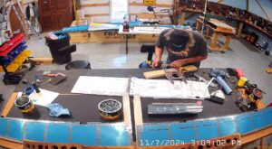
I used my bandsaw to rough cut the bar to the correct shape and dimensions and then 1″ belt 5″ disk sander purchased from Harbor Freight to complete the preparation. They have them in the store still but I don’t see them on the web site. They are pretty cheap.

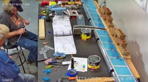
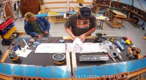
So we completed steps 1 through 3 first, then made the rudder cable angle in step 4 and the bulkhead stiffener F-1011A from one of the 6 foot J channel lengths provided. It is important not to use one of the 8 foot lengths because you need to cut 90 3/4, 90 11/16 & 90 5/8 lengths on page 10-5.

TC: Page 10-2, Steps 1 Through 3. Make Tie Down Bar & F-1011E Rudder Cable Angle
TC: Page 10-2 Step 1. Tapping The 3/8-16 Tie Down Bar.
TC: Page 10-2, Steps 1 Through 3. Make Tie Down Bar & F-1011E Rudder Cable Angle

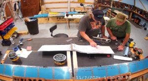
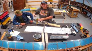
Next comes the F-1011C horizontal stabilizer bars. They are a little bowed as a consequence of being made so the first step is to flatten them. I did as recommended in step 1 of page 10-3 with frequent checking to make sure I wasn’t bending the bar too much.

TC: Page 10-3 Steps 1 Through 3. Straighten & Attach Horizontal Stabilizer Attachments & Bulkhead Stiffener

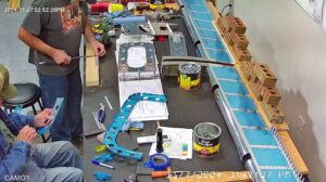
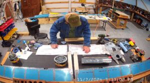
Page 10-3 is completed with steps 4 and 5 which comprise the drilling out of 2 * 1/4″ holes to 5/8ths and locating and match drilling the rudder cable angle attachment F-1011E to the F-1011 bulkhead.

TC: Page 10-3, Steps 4 & 5. Completing F-1011E Attachment & 5/8ths Step Drilling in F-1011 Bulkhead.

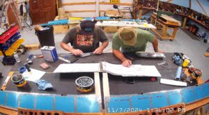
On Page 10-4 the first step is to make the F-1010A horizontal stabilizer attachment bracket from AA6-125x1x1 angle supplied. The kit supplied angle did not have a label on it but if you’ve been to a workshop and / or read any of the handbook for aircraft mechanics, plus section 5, you can determine which piece of angle is the correct piece.

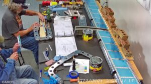
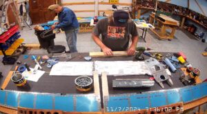
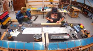
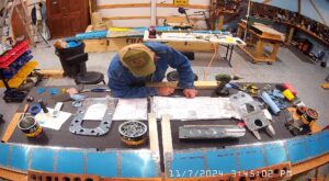
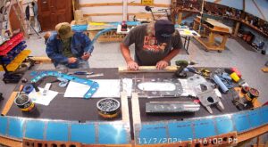
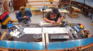
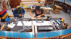
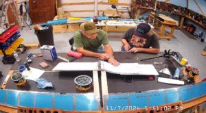
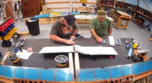
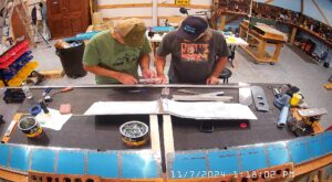
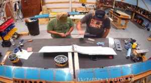
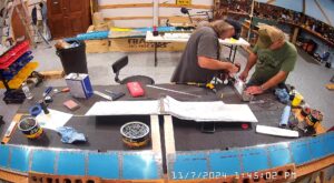
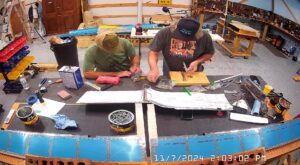
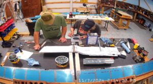
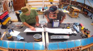
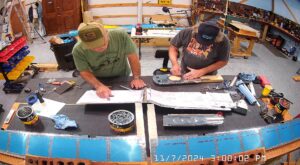
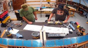
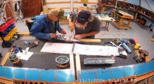
EJ and I made the angle and also removed the vinyl and deburred the various bulkhead pieces, doublers, attaching and final drilling holes etc. completing all the steps on page 10-4, 1 through 5 and step 1 on page 10-5.

TC: Page 10-3,4 & 5 Through Page 10-5 Step 1. Prepare Bulkheads, Doublers, Rudder Cable Bracket F-1085

Leave a Reply

Your email address will not be published. Required fields are marked *