DATE: 12-19-2024 TIME: 2:51 – 5:21 ~ 2:30
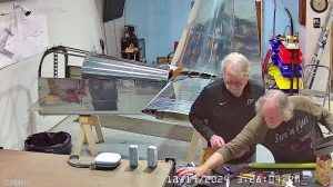
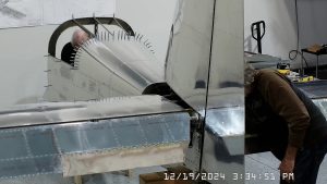
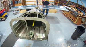
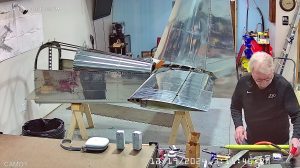
Today we continued the RV-10 empennage assembly with completing the push rod assembly and then attaching it to the elevators and bellcrank per steps 4, 5 and 6.
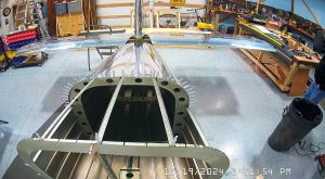
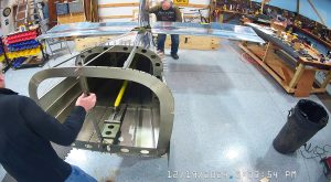
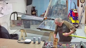
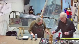
Joe was back so I had him rivet the threaded inserts into the rod ends and then threaded the rod end bearings into the inserts and set the lengths as specified in step 4 before placing the rod into the tailcone and attaching the ends to the elevator horn at the rear and the bellcrank in the forward position.
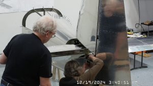
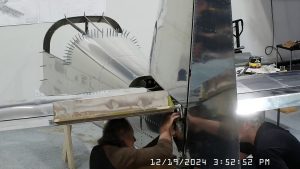
The only tough part of this process is getting the bolts and washers in place to bolt the bellcrank to the elevator horns.
Once installed, you have to again check for the correct amount of elevator travel per page 11-2 figure 4. I just want to note here that you need to check the amount of elevator travel relative to the horizontal stabilizer chord, not “ground level”. Depending on how you have your tailcone setup, if you are using a “smart” level, as I did, you could get totally erroneous range of rotation measurements if the range of motion is relative to ground / floor level instead of the chord. Just an FYI for someone who hasn’t done this before.
We did not have any meaningful deviation from the range of motion required so did not need to make any further adjustments to the elevators.
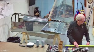
The next step is to adjust the push rod at the bellcrank to the template in the manual. I made a photocopy, actually scanned and reprinted, the template in the manual and then used that to cut a piece of light cardboard as the measuring template. We had an 1/8th of an inch at the bottom corner of the template so adjusted the pushrod a little longer by unscrewing the forward rod end bearing a turn or two and then locking the jam nuts at both ends.
The manual says to now remove the push rod and store it. We did not do so and as of right now, the push rod is still in place. We may have to remove it as we proceed but if we don’t, I am just as happy to leave it installed.
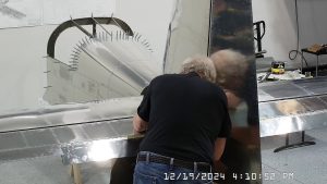
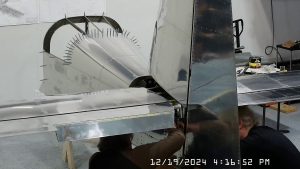
We had already installed the rudder the previous day so we set about checking the turn radius to make sure it was within limits as described in figure 5 on page 7. We were not within the limits but due to time constraints did not complete the adjustment process today.
