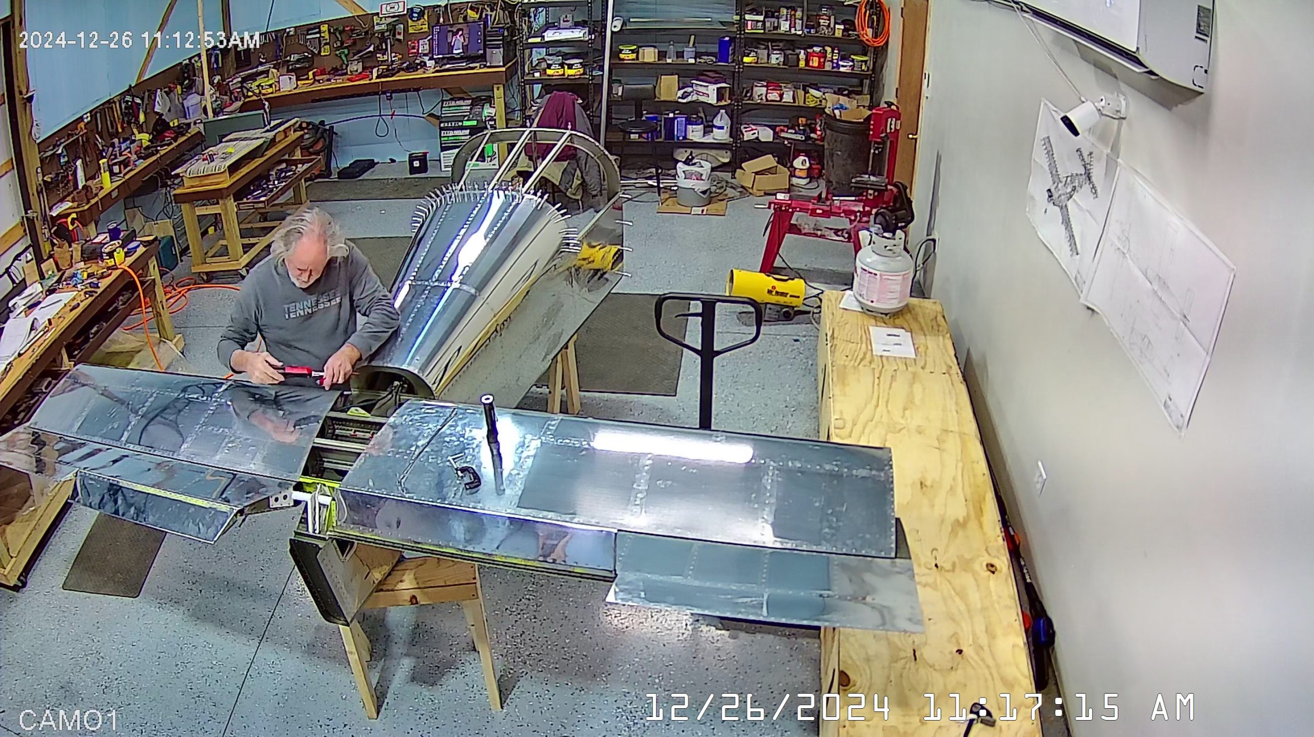
DATE: 12-26-2024 TIME: 10:13 – 4:54 p.m. ~ 5:30
I have titled this as continuing the empennage assembly on page 10 of section 11 but in reality it also encompasses some of the work on page 9.
As mentioned in my previous post, I thought I had stripped one of the nut plates on the F-1095A trim tab actuator assembly mounting plate. Once I had it removed, I discovered that, thankfully, the nut plate was fine but the screw needed to be replaced. Rather than pulling the cables out from through the elevators and horizontal stabilizer I disconnected them from the bell crank and the F-1095 sub assembly and left them in place.
When attempting to reattach the F-1095 assembly I discovered that the F-1095 was bumping up against the F-1010A frame and / or the F-1010B doubler which was preventing the match drilled holes from lining up correctly. This was the cause of the one screw becoming stripped in the first place, so I ran the F-1095A against my sanding disc to remove about 1/32nd of material (the thickness of a blue sharpie) from the rear edge and this was enough for me to get the F-1095A to seat correctly.
Having resolved that issue, I then reconnected the cables, beginning with the left trim tab. As I mentioned previously also, the cable shield is very stiff and was pushing the anchor on the rear cover plate away from lining up with the nutplates in the elevator. If it were me, I would have made the cable shield lengths at least 3/8th inch shorter, or maybe the whole cable. In the end, what I did was unlock the cable nut at the F-1095 end push the cable further through the F-1095G anchor brackets. The instructions say “about half way”. With my cables only set 1/2 way into the brackets they create way too much stress at the E-616PP end making it virtually impossible to screw the cover plate in place.
One other thing, the instructions on page 10, step 3, say to thread the cover plate onto the cable. This is also very difficult to do because of the rigidity of the cable and the short length protruding out from the elevator. I found that after I had replaced the F-105 assembly into the tailcone, and before anchoring the cables at that end, it was much easier to thread the cover plates onto the cables and then set the cable length so that there was minimal to no stress on the cover plate once screwed in place. After that, I went back to the F-1095 and anchored the cables at that end. It is a little difficult to get the rod ends / cable ends back into place on the bellcrank, but I managed to do this reasonably quickly entirely on my own. When tightening the nuts on the bellcrank I used duct tape to hold an open wrench on the bolt and used a small 1/4″ drive socket on the nut.
Next came the adjustment of the cable so that the trim tabs were moving according to spec. I used a quick clamp to hold the elevators in the trail position and then struggled to get the 35o deflection angle. Once I had that on the left tab, I started on the right and then activated the actuator only to find that while the left tab stops in trail position, the right tab keeps rising. Sadly, the instructions here are completely deficient. They don’t mention the tabs deflecting about the elevators at all.
I did a search on Vans Airforce where I found a couple of excellent posts and links with respect to setting the trim tabs. I include the links here in case you need them. This is a most complete article here: https://www.myrv10.com/N104CD/maintenance/20080622/index.html, the link and other comments can be found on Vans Airforce.
Personally, I think what they did with the elevator trim is a dogs breakfast and the “instructions” reflect that. Thw whole thing looks very much like an afterthought. Split tabs just seems crazy and then that is made worse by having a bellcrank system that doesn’t allow for completely symmetrical movement when it would have been just as easy / and or cheaper to make them symmetrical in both nose up and nose down movement.
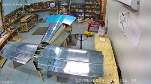
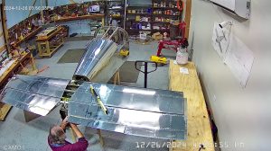
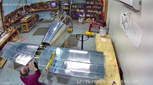
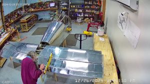
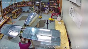
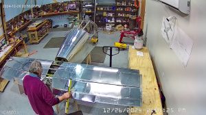
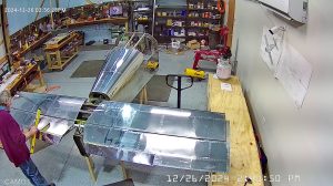
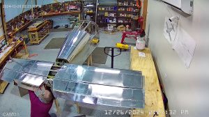
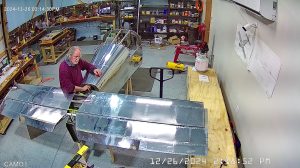
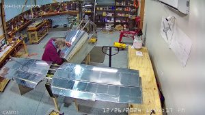
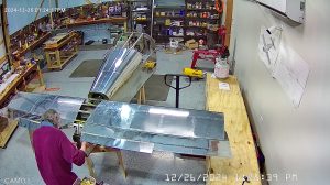
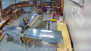
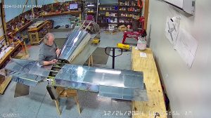
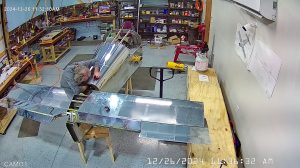
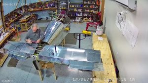
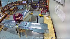
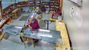
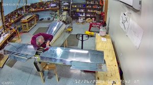
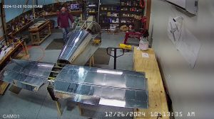
Before you ask, yes, I used a torque screwdriver and a click type torque wrench to properly torque all screws, nuts and bolts. You will see in these snapshots that I re-attached the forward skin. I did this to provide more rigidity to the frame as my plan was to suspend the tailcone from the roof – see the next post.
Well, here the remaining photos of me working on the trim tab and tail cone. At the end of this process I put the RV-10 to bed so that I can focus on building my wife’s Zenith 750 SD (super dooper as she calls it).
