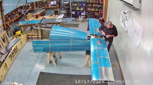
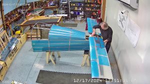
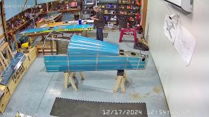
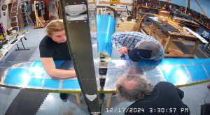
DATE: 12-17-2024 TIME: 11:44 – 05:07 p.m. ~ 5:00
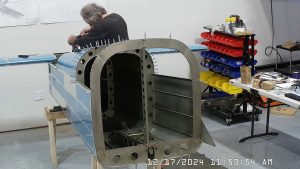
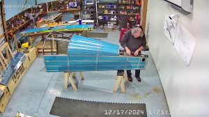
My Aircraft Spruce order for the 6″ extended reach #12 cobalt drill bit, and a couple of other small items, arrived on the 16th but I had a number of other issues to deal with so did not get back to the RV-10 empennage assembly until this morning, picking up with match drilling the F-1008, shims and F-1014 aft deck. This also drills through the bulkhead and spacer, hence the depth and requirement for a longer drill bit.
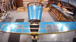
Having left the assembly for a few days I started by remeasuring the alignment of the horizontal stabilizer. As I have been going through this building process it has become very clear that double and triple checking before you do anything can actually be a lot faster, and cheaper and less frustrating, than having to redo some botched job.
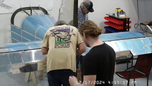
That isn’t a long process so the cameras that take time lapse images don’t capture all of the activity.
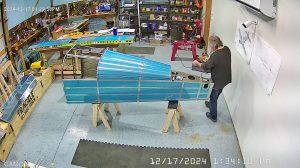
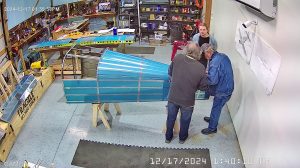
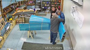
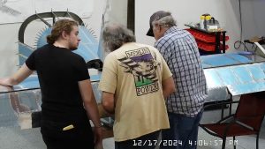
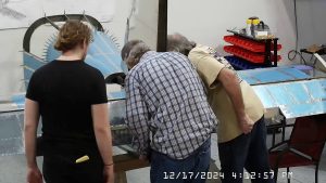
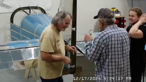
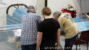
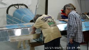
Friend Joe had taken off to a memorial service for a friend in Indiana so I started the day on my own but trusty assistant EJ and his grandson Ty arrived a little later to help. Just as well, I really did not want to lift and move the horizontal stabilizer on my own but in the end that is what I did after removing the bolts from the F-1011C brackets. Then I primed the shims and the VS-1016 attachment plate. For small prime jobs I have a Zinc phosphate primer rattle can so that I don’t need to mix P60G2. Although it’s a different colour it’s not a major issue in my view, particularly as it will not generally be visible.
I also took the opportunity to apply some thread locker to the bolts and then re-torque them as appropriate.
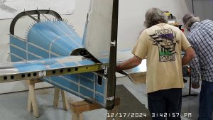
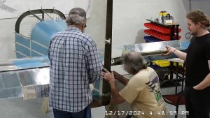
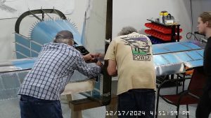
By now EJ and Ty had arrived and it was time to put the horizontal stabilizer back in place, permanently bolt it down, and attach the vertical stabilizer front attachment plate VS-1016 per step 4.
Unfortunately, the manual is a little inconsistent with respect to when it says to temporarily attach something that will need to be removed again and when it does not. As a consequence, and because the horizontal stabilizer now appeared to be permanently attached, when the instructions said to attach the vertical stabilizer I assumed it to be a permanent, or final, attachment. This is NOT the case. Additionally, I have no idea why the instructions say to bolt the vertical stabilizer in place before attaching the elevators. If you attach the vertical stabilizer in step 5 on page 11-5 it is far more difficult to attach and torque the elevators and trim tab to the horizontal stabilizer than it would be to first attach the horizontal stabilizer and then the vertical stabilizer and do the final drilling and attachment of the vertical stabilizer.
Having said that, if you do decide to change the order and attach the elevators to the horizontal stabilizer first, do a thorough review yourself to determine which is more appropriate. I would also note that further on in section 11, after having attached the rudder and checked the range of motion and made any adjustments, the instructions say to remove both the rudder and the vertical stabilizer and to store them somewhere, thus leaving the horizontal stabilizer and elevators in place.
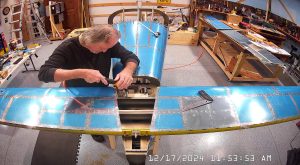
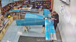
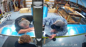
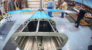
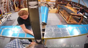
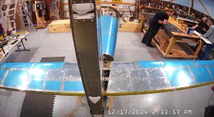
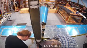
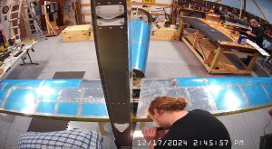
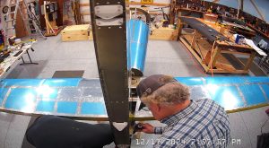
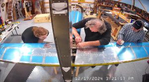
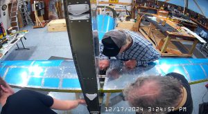
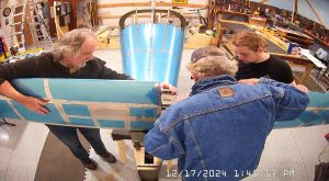
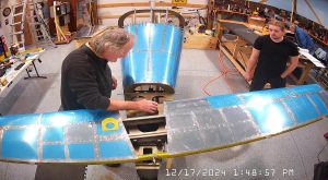
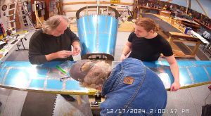
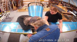
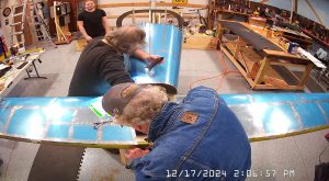
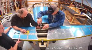
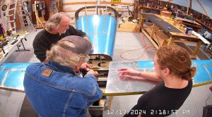
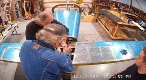
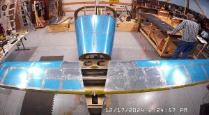
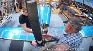
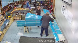
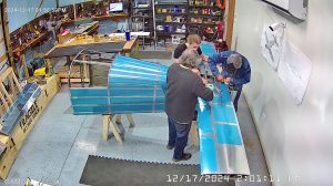
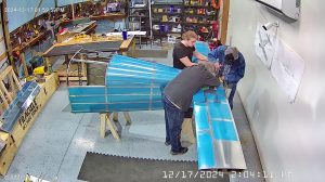
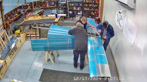
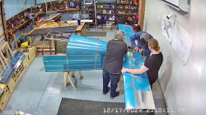
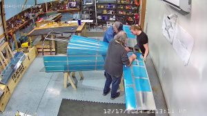
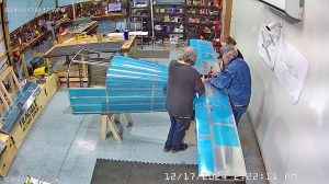
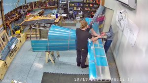
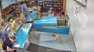
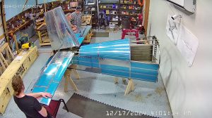
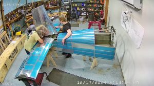
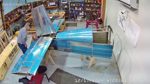
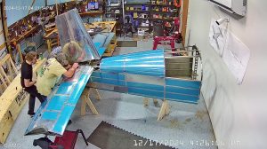
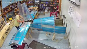
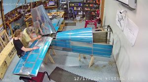
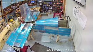
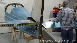
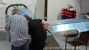
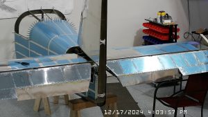
Here are the snapshots of the processes called out on page 11-5, step 4, attaching the VS-1016 to the HS-1002 front spar, and step 5, attaching the vertical stabilizer and final drilling as required the holes in the vertical stabilizer rear spar and match drilling the F-1012 aft fuselage bulkhead assembly and attaching with the hardware defined.
The AN509-10R11 machine screws at the bottom of the vertical stabilizer rear spar assembly are very difficult to insert and torque.
Step 1 on page 6 is to apply some anti-seize paste to the VS-1016 and bolt the vertical stabilizer to the bracket.
Note again that even though there is no indication they want you to remove the vertical stabilizer again, later in section 11 you are instructed to do just that so don’t use any thread lock on any of the vertical stabilizer attach bolts and screws.
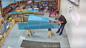
Next step, page 6 step 2, is to attach the elevators to the horizontal stabilizer. For ease of access and snapshot purposes we turned the tailcone around again so that the horizontal and vertical stabilizer and rudder would be out in the middle of the floor rather than pressed up against the wall.
Bolting the elevators to the horizontal stabilizer is a pain in the neck, primarily the central bearing depicted in detail C on page 11-2. It’s a pain because of all the washers. It can be made worse because when you are drilling the elevator horns per the step 1 instruction on page 11-3 if you have not properly set the rod end bearings in the elevators, the nut and bolt head threaded through the bearing are going to end up too close to the horn rod and / or weld, to be able to get a ring wrench or, preferably, a socket onto the head.
When I drilled the holes per the instructions on page 11-3 for the VA-146 centre bearing I had been careful to set the rod end bearings in the elevators to the specified 7/8th inch to the centre of the rod end as measured from the front of the HS-1002. I then used the E-DRILL bushing to drill the hole in the left elevator horn, removed the left elevator and repeated the process for the right elevator horn. Reassembled everything and, even though the bolt went through easily enough, there was not enough clearance between the bolt head, or the nut, and the weld and horn rod to get a socket onto either the AN4-13A bolt head nor the AN365-428 nut. I had a little more clearance on the left elevator horn and, after filing a socket down to a “thin walled” socket, was able to get it onto the nut with the nut on the left and the bolt head on the right. I had to use an open wrench on the bolt head on the right.
I am explaining this because, if I had to do it again, I would make sure, before drilling any holes in the elevator horns, that I had enough clearance to get at least a thin walled socket of the appropriate size on both the bolt head and the nut, even if it meant having the rod end centres 15/16ths or as much as an inch from the HS-1002 front spar. Once the holes are drilled, it is too late to make any changes because you can’t exactly replace the elevator horns and you cannot just drill new holes either.
The difficulty created by not being able to get a socket onto both the head and the bolt is exacerbated when you are trying to reattach the elevators to the horizontal stabilizer with the vertical stabilizer already in position as the vertical stabilizer further obstructs access to the bolt and nut through the VA-146 centre bearing.
Having spent quite some time trying to get the AN4- bolted back up through the VA-146 centre bearing without much luck, even after making a “thin wall” socket out of one of my sockets, I called it a day and went off back to Harbor Freight to buy a set of universal drivers which included a 1/4″ universal drive and left the completion of the elevator re-attachment to the following day.
When we first attached the elevators to the horizontal stabilizer and measured the rod end reach at 7/8ths as specified we then checked the range of rotation and everything seemed just fine but clearly the rod end was at least 1/16th too short for the purposes of the centre bearing bolt.
