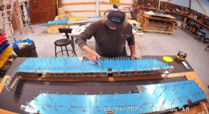
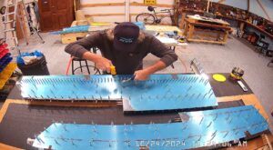
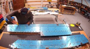
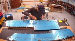
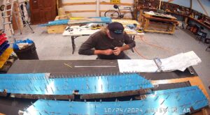
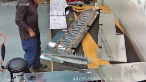
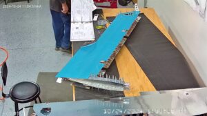
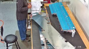
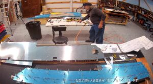
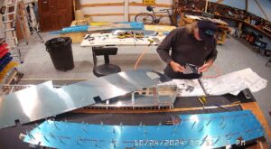
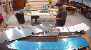
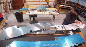
DATE: 10-24-2024 TIME: 09:16 a.m. – 4:58 p.m. ~ 7:00 hours
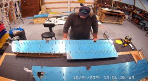
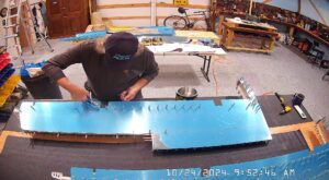
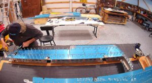
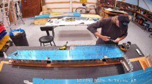
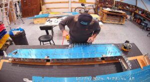
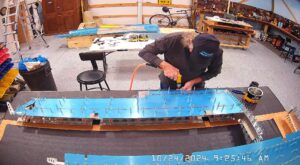
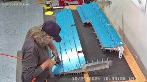
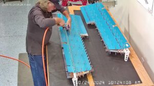
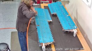
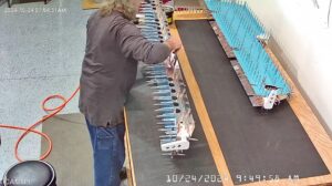
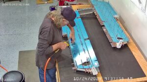
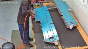
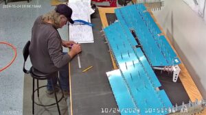
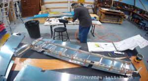
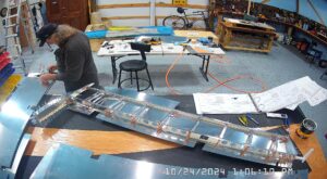
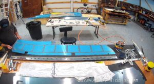
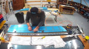
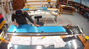
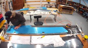
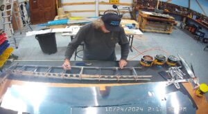
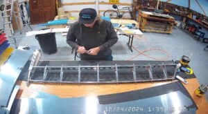
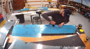
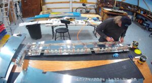
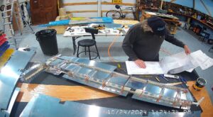
I got an early start on trying to get the elevator assembly completed beginning with finishing off the final drilling of the skins and spars per steps 1 through 3 on page 9-7. I had completed the prep and some of the drilling the day before.
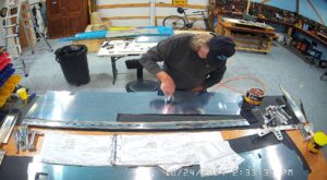
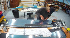
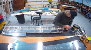
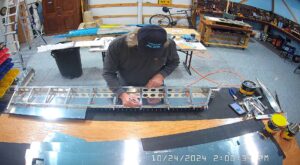
Step 4 on page 9-7 is the placement of the WD-415 trim cable anchor brackets (with welded nuts in place), onto the cover plates. These are placed as close to the centre of the cable entry slot as possible and then you drill four holes in each bracket and through the cover plate.
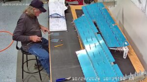
It’s very difficult to hold the brackets in place while you drill them, at least on a drill press as I did, so I measured and marked everything up. Drilled one hole very carefully through both the bracket and the cover plate and then put a cleco in it before drilling the remainder. The rivets used to attach the bracket are LP4-3 blind rivets so you don’t really have to be too concerned about drilling too close to the weld but you definitely don’t want to be too close to the edge of the bracket.
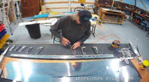
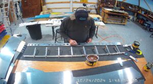
I spent quite a bit of time sorting the various nut plates and putting them into handy little kitchen seal bags and labeling them. There are a number of different styles and sizes in the empennage kit so you need to be careful the you attach the correct one. The Cover plate holes need to be dimpled for the screws and the reinforcement plate for the nutplate attachment holes and all the rivets. The nutplates also need their attachment holes dimpled although the scew hole in the nutplate is manufactured to accept a dimpled screw attachment.
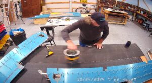
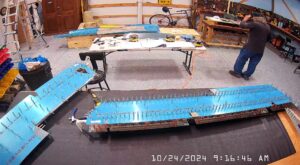
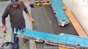
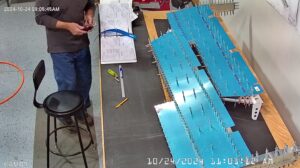
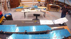
At this point the elevator assembly is completely disassembled, any remaining deburring has to be completed and the skins and spars, stiffeners and ribs and all other dimpling needs to be completed prior to priming.
I found this section of the manual extremely frustrating. Step 9 simply says – Dimple the holes in the E-1001A & B skins (don’t forget the three holes in the close out tabs), and the E-913 Counterbalance skin. Whereas in previous sections of the manual if certain holes were not to be dimpled, the manual said so. However, there are definitely 7 holes in the counterbalance skin that should not be dimpled because they still have to be drilled out for the elevator tip fairing. The fact that this isn’t mentioned caused me to spend an inordinate amount of time verifying everything that really needed to be dimpled. The same situation occurs on page 9-9 where the instructions say to dimple the flanges of the E-903 tip rib and counterbalance rib. More on that later.
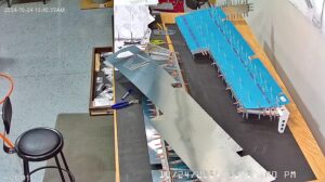
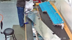
Unfortunately, my camera on the dimpler was not capturing images so I don’t have any close up images of the dimpling process itself, or if I do they are somewhere on the computer and I have yet to find them. If I do find them I will add them to the gallery.
