I bought the Vans Aircraft Tool Box when I first decided to build a Vans Aircraft RV-7A. I purchased the preview plans for the 7A in about 2005 and then, after some delays, purchased a complete Vans tool kit from Avery in about 2010, along with the Vans Aircraft Tool Box in 2010 or ’11.
Now, 12 years or more later, having completed the workshop build out, I finally started on my practice kits. It was almost a moot point, or so I thought, as I had been to an EAA / Sportair metal airplane workshop and also had a copy of the EAA DVD. Here is my experience.
Having just completed one of the smaller simpler kits I had come to realize how important reading, and re-reading the instructions can be. This really came home with the reading of the tool box instructions.
Remove the plastic coating and deburr the edges of ll the parts.
P1
OK, that was simple enough. I used my 3M wheel and it took no time at all.
Cleco the ends to the outside of the tool box body with a cleco in every other hole. Match drill the open holes with a #40 drill, move the clecos to the open holes and match drill the rest. Deburr both sides of all the drilled holes. Mark one end left and the other right. Dimple the end hole in the body and in the ends with 4263 dimple die set making sure to dimple the outside of the Left and Right ends.
P2
OK, that was pretty simple too although this time for deburring we used the Avery designed offset cutter and handle, an item now available from Aircraft Spruce since they bought Avery Tools.
I had purchased a pneumatic drill with variable speed trigger. Quiet, fast and light, a real joy to use.
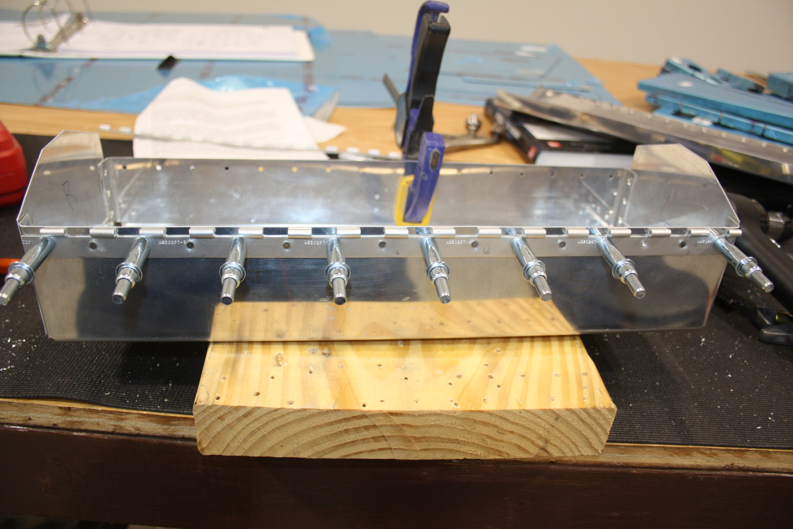
I should also explain that, as learned at the metal workshop, I had prepared a bracket and clamp to hold the tool box steady. It turns out I did not need it at this juncture as I had my friend Joe, a pilot from Lakeland, to help.
Next, we riveted the ends to the body as instructed. I had purchased a Red Box x3 rivet gun, set and bucking bar set. This proved to be confusing initially due to the way the sets in the box were marked (16ths) compared to the rivets (32nds)
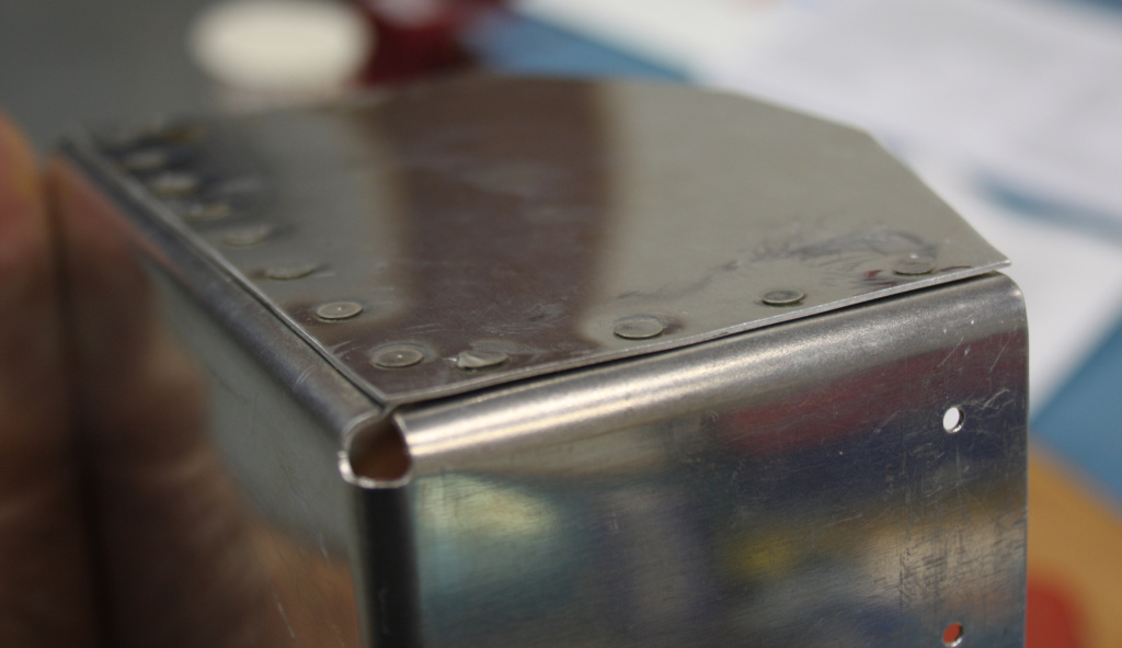
Compare this next image with the one above and note the difference…there i less gap between this side panel and the box itself. It is important to have pieces properly deburred and clamped or cleco’d together before riveting. Also, if you used too much pressure on the pneumatic riveter it will distort the metal and you will end up with a wavy rivet line.
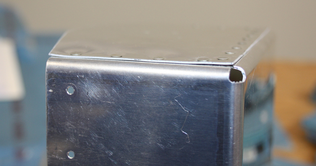
Rivet the ends to the outside of the body with AN426AD3-3.5 flush rivets. (3/32 flat head).
P3
The next paragraph brought the first real challenge…
Cleco the front stiffener to the body with the bend towards the inside of the box. Reverse the hinge segments and determine the hinge length. The lid segment of the hinge fits inside of the lid flanges. The hinge segment for the lid will have the eyelets facing out from the body. Cut the hinge to length. Leave the pin long for now. Clamp the body segment of the hinge to the body with the eyelets even with the top edge of the box. Remove the front stiffener. Match drill the hinge and body with a #40 drill and cleco as you move along.
P4
There were two challenges for us in these instructions:
- What does “reverse the hinge segments” mean
- …eyelets even with the top of the box…
The second issue may have been easier to figure out if we had initially figured out what reversing the hinge segments really meant. As it is, we did not get it correct and ended up cutting the hinge incorrectly. Fortunately, it isn’t an aileron, elevator or rudder hinge and it was not so egregious an error that we had to replace the hinge. Below are some pictures of the hinge a it arrives and how it looks with the segments reversed.
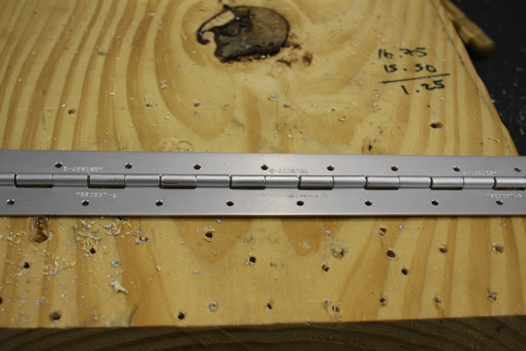
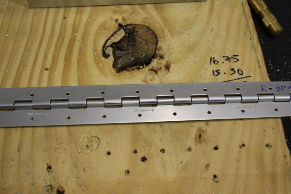
The second issue, aligning the eyelets with the top of the box, was made more confusing because of the initial confusion, but it would have been a question anyway. Align “what” of the eyelet with the top of the box ? The top, the centre, or the bottom of the eyelet ? After some experimentation, and re-reading the instructions, it became clear we had not understood what reversing the segments meant and then that led to properly aligning the top of the eyelet with the top of the box.
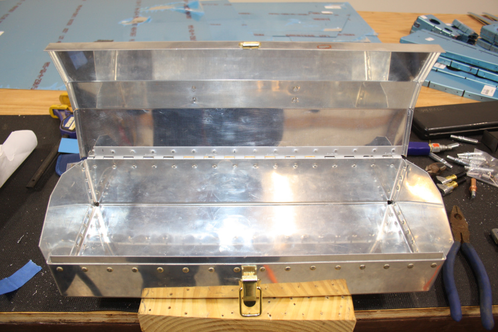
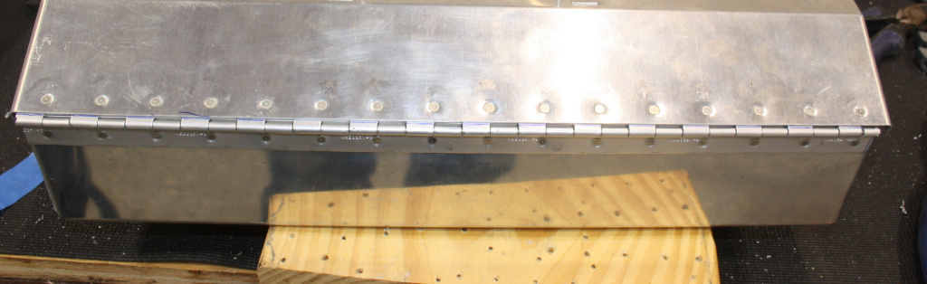
Replace the front stiffener with clecos. Position the lid and hinge in place and insert the hinge pin. Mark the position of the hinge on the top by drawing a line on the exposed eyelet with a Sharpie pen. Remove the hinge pin and the lid and clamp the top hinge in place. Match drill the hinge to the lid, Deburr all the holes in the lid and hinges. Dimple the body, the lid and the hinge segments making sure to dimple the proper side of the hinges. Rivet the hinges to the body and the lid with AN426AD3-3.5 flush rivets.
P5
You will notice that the instructions do not specify which drill to use for match drilling the nor which dimple die to use. You are supposed to either assume it’s the same as the #40 for match drilling the body hinge segment, and the same dimple die 4263, based on the rivet being used.
Now match drill the front stiffener with a #30 drill. Deburr all the holes and rivet the stiffener to the body with AN470AD4-4 universal rivets (1/8″ round head).
P6
That was simple enough, and straight forward. Maybe it is worth mentioning here that the smaller the drill number, the larger the diameter of the drill bit.
After drilling with a #30 drill and deburring the holes, rivet the bottom latch half to the body with AN426AD4-4 flush rivets (1/8″ flat head).
P7
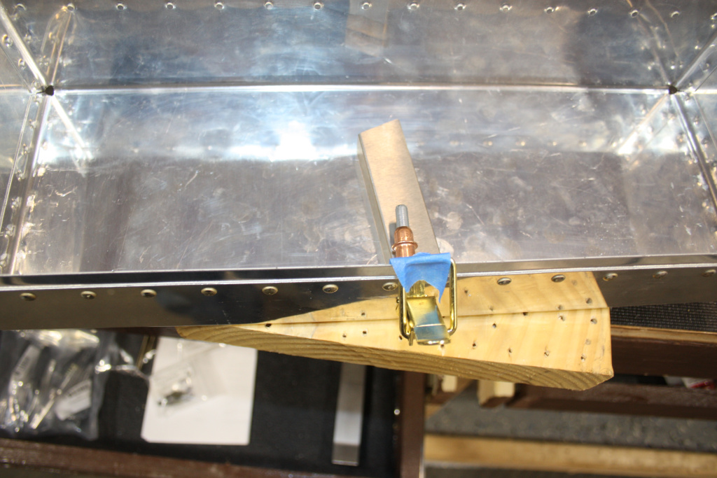
You will notice that the latch has been countersunk so no dimpling or countersinking is necessary. Just make sure you pick the correct rivet. You will note that I used blue painters tape to tape the latch to make it easier to rivet.
Put the top on the body and insert the hinge pin. Put the bottom latch half in the closed position and hold the hook portion up against the wire bail. Mark the hole position and drill the #30 holes for AN470AD4-4 universal rivets. Rivet the hook into place.
P8
This is pretty straightforward. Nothing really complex here.
Bend the handle from the .090″ hinge pin wire supplied using the drawing as a guide. You may heat the handle to make the desired bend.
P9
Place the handle and the handle clips on the box lid in position Mark one hole on each clip . Drill and cleco one hole in the clip, then the other hole. Deburr the holes. With the handle in place, and a cleco in one hole, rivet the other sied with and AN470AD4-4 universal rivet. Rivet the other side of the handle clip.
P10
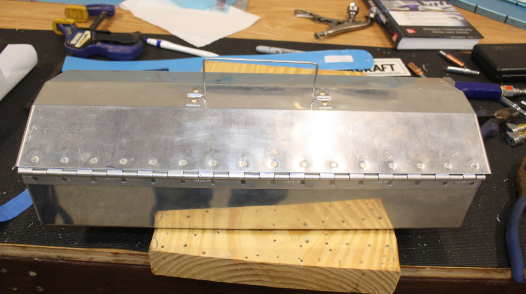
By the time I had reached this final leg of the assembly I was getting used to the imprecise nature of the instructions. As an individual who likes instruction to be absolutely clear, pedantic even, it was a little frustrating at times reading these instructions. So, I added the handle my own way. I started by shaping the handle, then I lay the handle on the lid, the lid being in the closed position on the box, with the clips lying over the handle on either side. I then used a steel rule to get the handle clips equidistant from the left and right edge, marked all the holes, removed the handle, drilled one hole through each clip, after punching the location and hand turning the drill to make sure it didn’t spider across the lid, clecod the clips in place and drilled the second hole for each. Deburred the holes, riveted the left clip in place, placed the handle in place and then riveted to the right clip over the handle.
Cut the hinge pin 3/16th shorter than the total length of the hinge and slightly crimp the end hinge eyelets to retain the pin.
P11