DATE: 1/26/2025 TIME: 12:58 – 4:46 ~ 3:45
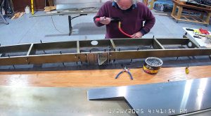
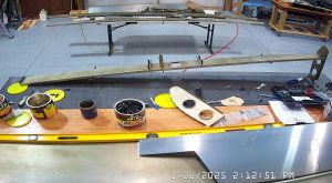
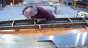
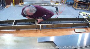
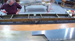
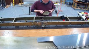
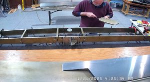
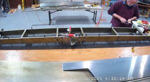
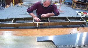
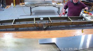
Assembling the Zenith 750 SD horizontal stabilizer continued today with the riveting of the rear spar bracket, hinge bracket and gusset to the rear spar and spar doublers.
I found, when trying to insert the (A6) 3/16th rivets, that the holes in the rear spar and the spar doublers were not sized for the rivets. Well, the spar may have been final sized but the doublers definitely were not. I drilled them to final size using a #12 bit.
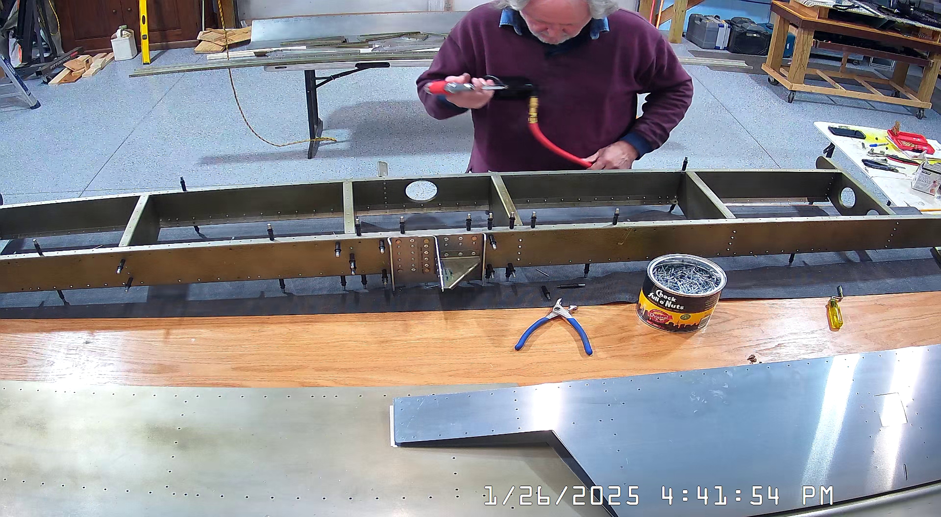
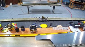
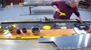
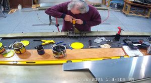
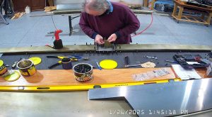
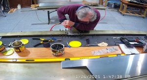
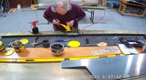
As I recall, some of the holes in the rear spar bracket were not final sized for the rivets either. Here are the pictures of the assembly process. After the pictures I have some comments that I feel make the IPL instructions provided by Zenith more accurate and more useful. It should be noted that these updates reflect the state of the tail kit as I received mine but the condition your tail kit arrives in may be different.
Instructions Update
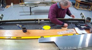
As mentioned previously, I had to final size drill the holes for the A6 (3/16th) rivets with a #12 bit. For this process I used a 6″ drill bit to make sure that I drilled as straight as I could next to the hinge bracket.
The IPL instructions have a rivet order for the components but they don’t mention which side of the assembly you should place the manufactured head of the rivet. Per Roger Dubberts instructions in one of his videos, if not stated, the manufactured head should be on the side of the thinnest material being riveted. In the case of the hinge bracket gusset I placed the manufactured head against the gusset. Later I found a photo where Zenith show the manufactured head against the rear spar and the shop head on the gusset side. I do not plan to change my rivets.
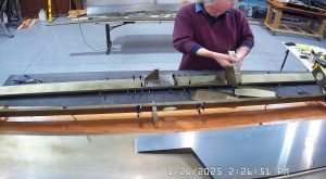
With regard to the order, the IPL instructions provide an order that has you trying to rivet the gusset to the hinge bracket when the hinge bracket is already bolted and riveted to the rear spar bracket and spar. This results in having to somehow get a hand riveter between the flange on the rear bracket and the hinge bracket, over the rivet mandrel. I did do this, but if I was going to build again I would rivet the gusset to the hinge bracket before bolting and riveting the hinge bracket in place.
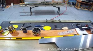
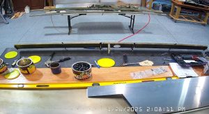
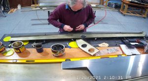
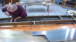
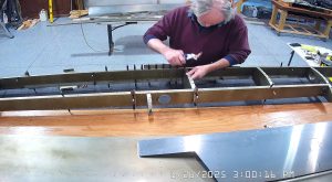
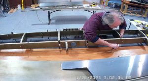
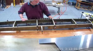
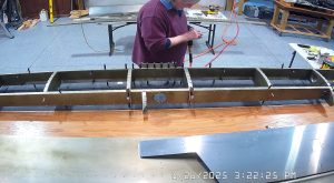
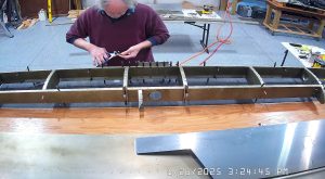
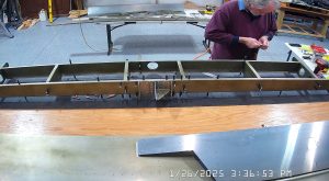
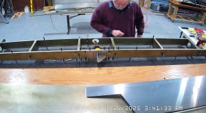
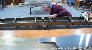
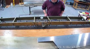
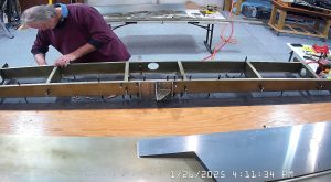
Below are pictures of the assembly of the ribs to the front and rear spar, after having clecod the skeleton together. It is really important to make sure you have the correct rear ribs in the correct places or the rib flanges will not be flush with the spar flanges. If you “lost” which end of the rib is the front and which the rear, start with placing the ribs so that the web of the rib is on the inside, toward the centre of the spar. Then, when you cleco the rib in place if the flanges are not flush, front and back, you have the wrong rib.
Here are my snapshots taken during the assembly process. The ribs are all attached with A5 rivets. If your kit arrives in the same condition as mine you will probably find that the rib holes are not sized for A5 rivets and you will have to drill them out. I used a #21 bit for this purpose. This is a pain if you have already clecod the skeleton together, particularly as you won’t be able to deburr the newly drilled hole so my recommendation is to check the rivet holes will accept the specified rivets before clecoing the parts together.